Radio / Amplifier
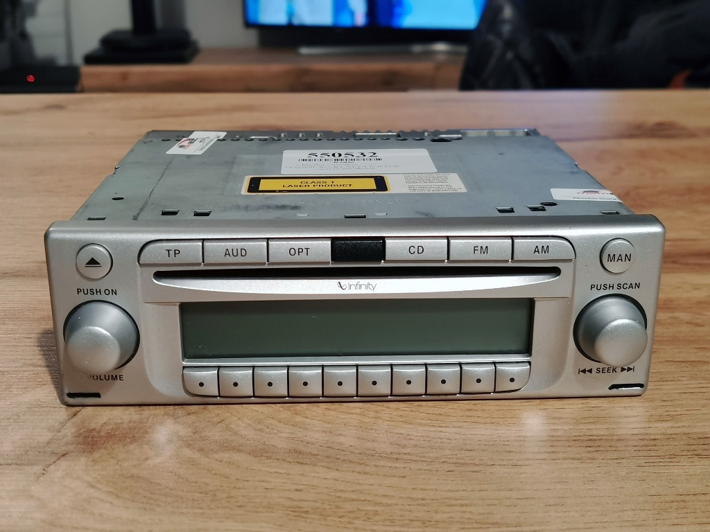
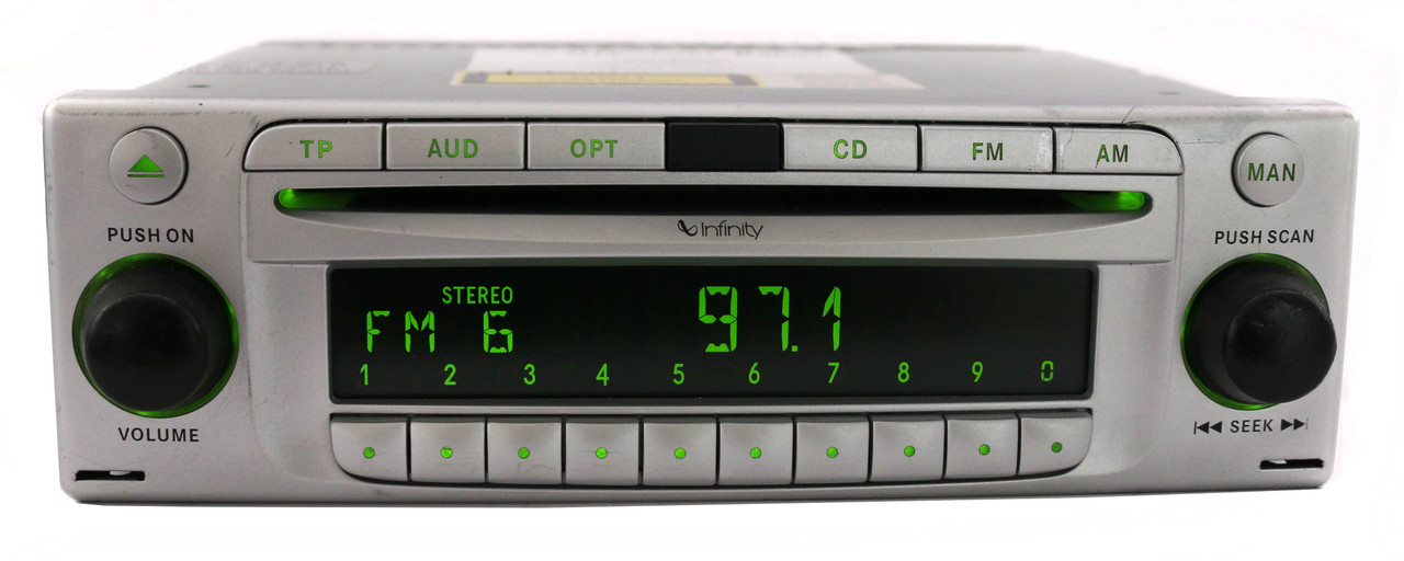
The crossfire is fitted with a Becker radio, based on the Becker DTM High Speed. The speakers on the non-Base models are powered by an additional Infinity Amplifier.
Radio
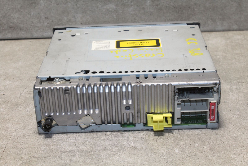
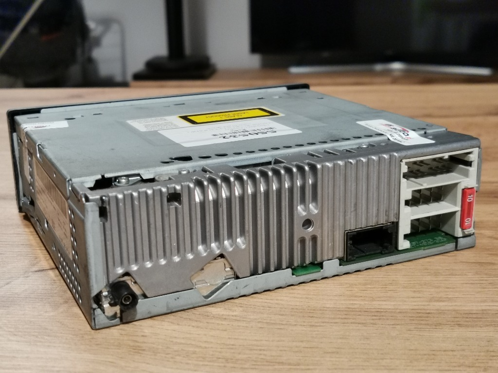
The radio itself seems to be based on the Becker Monza, and has all 3 connectors (A, B, C), although connector C is not used. Another spot for a MOST/D2B (Mercedes) connection can be found, but no fiber optics are installed (sometimes).
Some models do seem to include a MOST/D2B connection, as shown below.
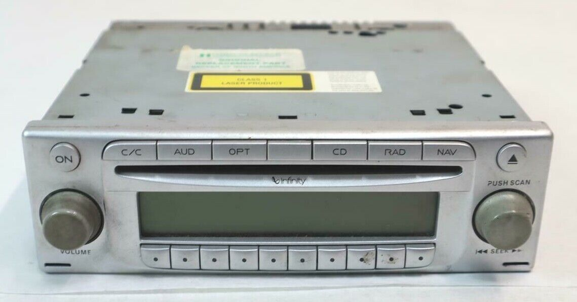
The NAV model has an additional C/C button, that is used for the CD Changer, a function that was never shipped with the crossfire. You can find documentation about the CD changer and installation here : https://www.crossfireforum.org/forum/audio-video-electronics/10953-cd-changer-nav-receivers.html .
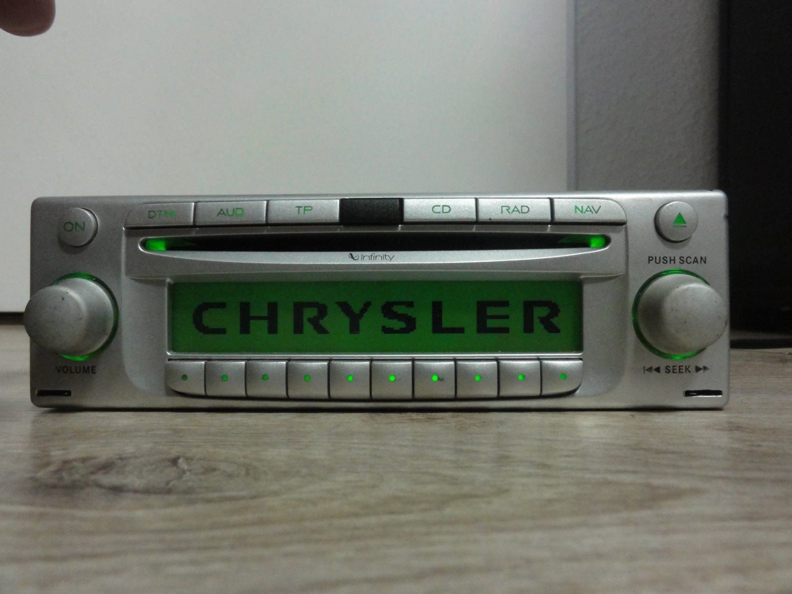
However, there are other variants that have a DTM button instead.
Part numbers
The Becker "ZH 29" type might refer to the Chrysler naming of the Coupe model, ZH29.
| Mercedes P/N | Notes |
|---|---|
| A 193 820 00 86 | (From SN 35002636)
BE 6806, Inverted screen, MOST cap, "Becker", DoM 19/03 (From SN 35006768) BE 6806, Inverted screen, MOST cap, "Becker", DoM 27/03 (From SN 35018394) BE 6806, Correct screen, MOST cap, "Becker" |
| A 193 820 03 86 | (From SN 45002935)
BE 6811, NAV option with C/C button, MOST/D2B capped off (metal plate), "Harman/Becker", No black spot on the centered tab, DoM 22/04 |
| A 193 820 04 86 | (From SN 45065224)
BE 6806, no NAV, MOST/D2B, "Harman/Becker" |
| A 193 820 06 86 | Late(st?) model, pulled from VIN 63677, no navigation, MOST/D2B connector. |
Amplifier
Wiring
4-channel configuration
As shown above, the amplifier does have 4 channels. However, the B connector on the Becker radio only wires the Front channels.
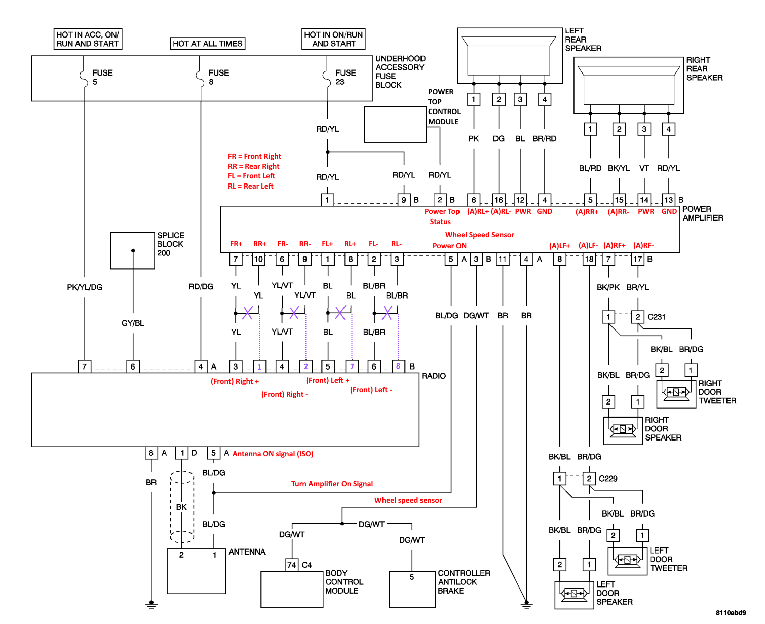
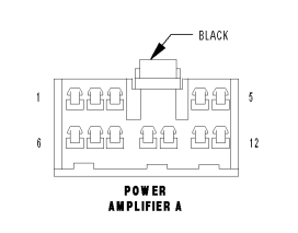
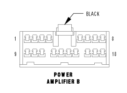
It is possible to pull 4 new wires for the rear speakers to the headunit, by cutting the following wires on the Power Amplifier A connector: 10 (RR+, yellow) 9 (RR-, yellow/violet) 8 (RL+, blue) 3 (RL-, blue/brown). Then, wire these to the radio on either RCA jacks or into the Radio B connector using "ISO radio connector pins".
