Difference between revisions of "CAN"
Jump to navigation
Jump to search
(Created page with "The Chrysler Crossfire has 2 CAN busses that is used to communicate between components, as explained below. {| class="wikitable" |+ CAN B BUS !Module !CAN B -!!CAN B + |- |''W...") |
|||
| (5 intermediate revisions by the same user not shown) | |||
| Line 1: | Line 1: | ||
The Chrysler Crossfire has 2 CAN busses that is used to communicate between components, as explained below. | The Chrysler Crossfire has 2 CAN busses that is used to communicate between components, as explained below. | ||
| + | |||
| + | More information here: http://www.carlogic.org/bg/data/MB%20CAN(ICC).pdf | ||
| + | |||
| + | ===CAN B=== | ||
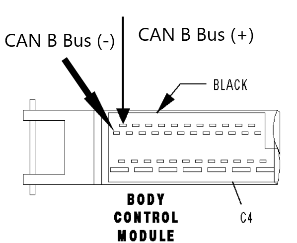
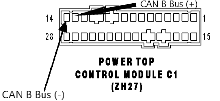
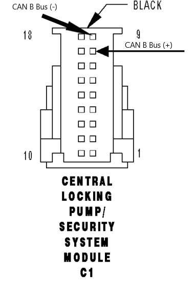
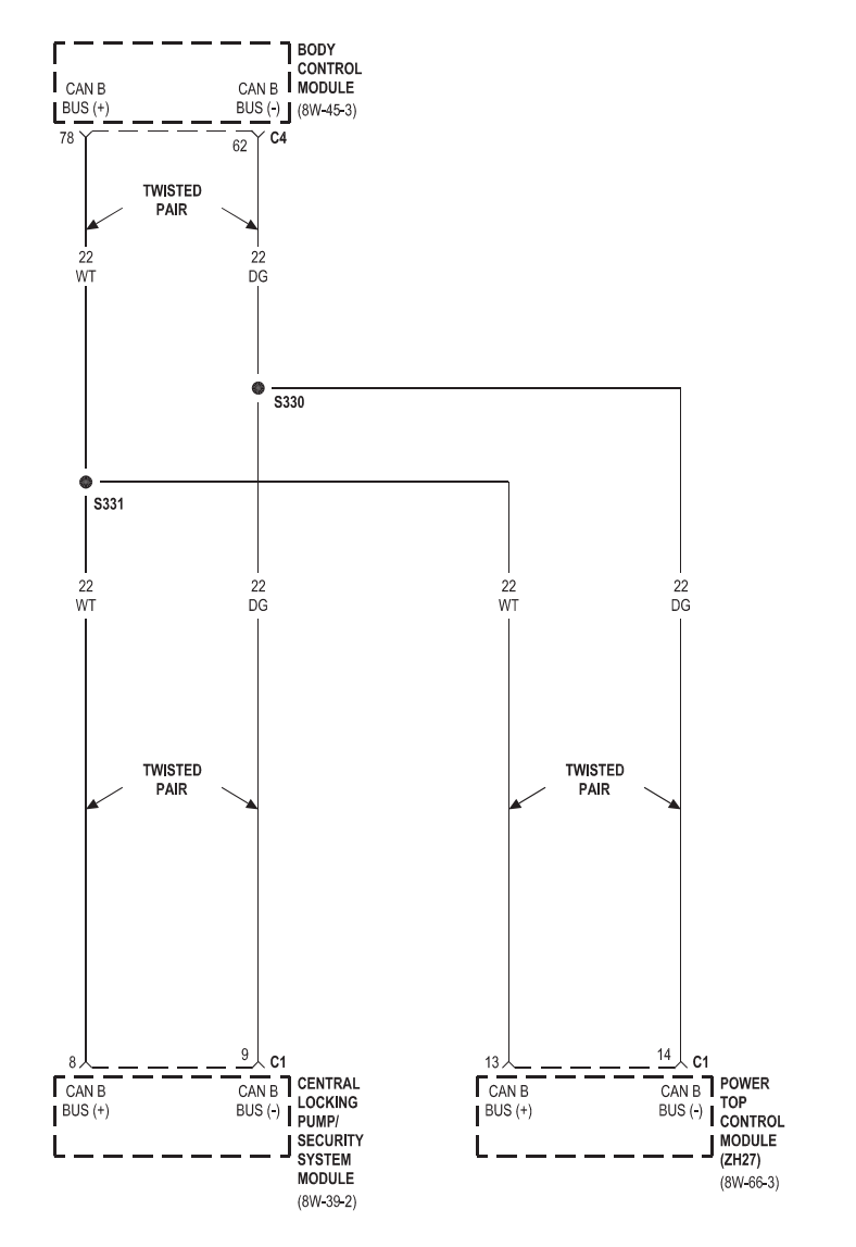
| + | This is the interior low-speed canbus, operating on 125Kbps. | ||
{| class="wikitable" | {| class="wikitable" | ||
|+ | |+ | ||
| Line 5: | Line 10: | ||
!Module | !Module | ||
!CAN B -!!CAN B + | !CAN B -!!CAN B + | ||
| + | !Picture | ||
|- | |- | ||
|''Wire Color as defined in 05 Service Manual'' | |''Wire Color as defined in 05 Service Manual'' | ||
|22 DG | |22 DG | ||
|22 WT | |22 WT | ||
| + | | | ||
|- | |- | ||
|Body Control Module (BCM) | |Body Control Module (BCM) | ||
|C4.62 | |C4.62 | ||
|C4.61 | |C4.61 | ||
| + | |[[File:BCM CAN B Bus pinout.png|thumb|Note: this is the inside of the connector!]] | ||
|- | |- | ||
|Power Top Control Module (PTCM) | |Power Top Control Module (PTCM) | ||
| + | Roadster only | ||
|C1.14 | |C1.14 | ||
|C1.13 | |C1.13 | ||
| + | |[[File:PTCM CAN B Bus.png|thumb]] | ||
|- | |- | ||
|Central Locking Pump (CLP) / Security System Module | |Central Locking Pump (CLP) / Security System Module | ||
|C1.9 | |C1.9 | ||
|C1.8 | |C1.8 | ||
| + | |[[File:CLP-SSM CAN B Bus.png|thumb|Note: this is the inside of the connector!]] | ||
|} | |} | ||
| + | [[File:CAN B Bus.png|none|frame]] | ||
| + | <br /> | ||
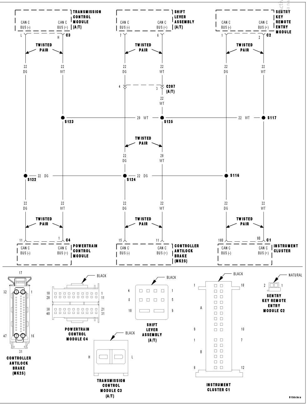
| + | ===CAN C=== | ||
| + | This is the high-speed engine/motor CAN bus, operating on 500Kbps. | ||
{| class="wikitable" | {| class="wikitable" | ||
|+ | |+ | ||
| Line 57: | Line 72: | ||
|6 | |6 | ||
|} | |} | ||
| + | [[File:CAN C Bus.png|none|frame]] | ||
| + | <br /> | ||
| + | ====CAN C bus data==== | ||
| + | |||
| + | =====PCM===== | ||
| + | |||
| + | *Engine coolant temperature | ||
| + | *Engine speed | ||
| + | *Engine load | ||
| + | |||
| + | =====CAB===== | ||
| + | |||
| + | *4 wheel speed signals (RPM) | ||
| + | |||
| + | ====CAN bus actuated indicator lamps==== | ||
| + | |||
| + | *Brake warning indicator lamp, which activates when the brake fluid is low, data comes from CAB | ||
| + | *Brake wear indicator lamp, which activates if the wear indicator inside the front brake pads is triggered | ||
| + | *Antilock Brake System (ABS) warning indicator lamp, which is on the side of the cluster, only turns on when the module is sensing something is wrong, and ABS will be engaged. Read DTC with DRB or other reader. Data comes from CAB. | ||
| + | *Malfunction Indicator Lamp (MIL/Check Engine), lights up when the PCM and/or the TCM report issues, data comes from PCM | ||
| + | *Oil level indicator lamp, data comes from PCM | ||
| + | *Electronic Stability Program (ESP) indicator lamp, data comes from CAB. | ||
| + | |||
| + | ====CAN bus actuated audible tones==== | ||
| + | |||
| + | *Parking brake warning | ||
| + | |||
| + | <br /> | ||
Latest revision as of 21:00, 16 November 2022
The Chrysler Crossfire has 2 CAN busses that is used to communicate between components, as explained below.
More information here: http://www.carlogic.org/bg/data/MB%20CAN(ICC).pdf
CAN B
This is the interior low-speed canbus, operating on 125Kbps.
| Module | CAN B - | CAN B + | Picture |
|---|---|---|---|
| Wire Color as defined in 05 Service Manual | 22 DG | 22 WT | |
| Body Control Module (BCM) | C4.62 | C4.61 | |
| Power Top Control Module (PTCM)
Roadster only |
C1.14 | C1.13 | |
| Central Locking Pump (CLP) / Security System Module | C1.9 | C1.8 |
CAN C
This is the high-speed engine/motor CAN bus, operating on 500Kbps.
| Module | CAN C - | CAN C + |
|---|---|---|
| Wire Color as defined in 05 Service Manual | 22 DG | 22 WT |
| Powertrain Control Module (PCM) | C4.11 | C4.1 |
| Sentry Key Remote Entry Module (SKREEM) | C2.1 | C2.2 |
| Controller Antilock Brake (CAB) | 15 | 11 |
| Instrument Cluster (IC) | C1.10B | C1.9B |
| Transmission Control Module (TCM) (AT only) | C3.L | C3.H |
| Shift Lever Assembly (SLA) (AT only) | 7 | 6 |
CAN C bus data
PCM
- Engine coolant temperature
- Engine speed
- Engine load
CAB
- 4 wheel speed signals (RPM)
CAN bus actuated indicator lamps
- Brake warning indicator lamp, which activates when the brake fluid is low, data comes from CAB
- Brake wear indicator lamp, which activates if the wear indicator inside the front brake pads is triggered
- Antilock Brake System (ABS) warning indicator lamp, which is on the side of the cluster, only turns on when the module is sensing something is wrong, and ABS will be engaged. Read DTC with DRB or other reader. Data comes from CAB.
- Malfunction Indicator Lamp (MIL/Check Engine), lights up when the PCM and/or the TCM report issues, data comes from PCM
- Oil level indicator lamp, data comes from PCM
- Electronic Stability Program (ESP) indicator lamp, data comes from CAB.
CAN bus actuated audible tones
- Parking brake warning
