Difference between revisions of "Data Link Connector"
| Line 181: | Line 181: | ||
Source Address: 0xF1 (tester) | Source Address: 0xF1 (tester) | ||
| − | Destination Address: 0x69 | + | Destination Address: 0x69 "DriverInformationDisplays9" |
{| class="wikitable" | {| class="wikitable" | ||
|+ | |+ | ||
| Line 396: | Line 396: | ||
Source Address: 0xF1 (tester) | Source Address: 0xF1 (tester) | ||
| − | Destination Address: 0x72 | + | Destination Address: 0x72 "Lightning2" |
'''Also supported through WiTech w/o drb 3 emulator''' | '''Also supported through WiTech w/o drb 3 emulator''' | ||
Revision as of 14:09, 29 April 2024
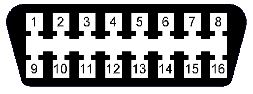
The Data Link Connector is the connector that you use to read the Diagnostic Trouble Codes (DTCs) from the car, using a tester such as Bosch ESI[tronic], Mercedes Benz StarDiag, or DRB III. Its plug is the same as an OBD2 / J1962 connector.
Pinout
Below is the pinout of the Data Link Connector. The naming is taken from the Service Manual (SRT6).
| OBD2 Pin | OBD2 Name | Circuit | Connector Pin Name | Attached Module |
|---|---|---|---|---|
| 1 | 20BK/WT | "SCI Transmit" | "SCI Transmit" from Body Control Module (BCM)
"SCI Transmit" from Sentry Key Remote Entry Module (SKREEM) | |
| 2 | J1850 Bus + | - | - | - |
| 3 | 20DG/YL | "SCI Receive" | "SCI Receive" from Powertrain Control Module (PCM / ECU / ECM) | |
| 4 | Chassis Ground | 18BR | "Ground" | - |
| 5 | Signal Ground | 20BR/YL | "Sensor Ground" | "Sensor Ground" from Fuel Tank Pressure Sensor
"Sensor Ground" from Powertrain Control Module |
| 6 | CAN (J-2234) High | - | - | - |
| 7 | ISO 9141-2 K-Line | 22BL | "SCI Transmit" | "SCI Transmit" from Powertrain Control Module (PCM / ECU / ECM) |
| 8 | 20RD/WT | "Fused Ignition Switch Output" | "Fused Ignition Switch Output" from Relay Control Module | |
| 9 | 22RD/YL | "SCI Transmit" | "SCI Transmit" from Controller Antilock Brake (ESP / BAS)
"SCI Transmit" from Shift Lever Assembly (SLA) | |
| 10 | J1850 Bus - | - | - | - |
| 11 | 22DG | "SCI Transmit" | "SCI Transmit" from Transmission Control Module (TCM / TCU) | |
| 12 | 20BK/YL (ZH27) | "SCI Transmit" | "SCI Transmit" from Power Top Control Module (PTCM) | |
| 13 | 20YL | "SCI Transmit" | "SCI Transmit" from Occupant Restraint Controller (ORC) | |
| 14 | CAN (J-2234) Low | - | - | - |
| 15 | ISO 9141-2 L-Line | 22BK/BL | "SCI Transmit" | "SCI Transmit" from Instrument Cluster (IC)
"SCI Transmit" from Universal Garage Door Opener / Tire Pressure Monitor "SCI Transmit" from A/C Heater Control Module |
| 16 | Battery Power | 18RD/DG | Fused B(+) |
Adapter pinouts
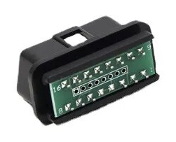
OBD2 8-pin adapter
Can be bought on Ali Express
| Pin | OBD-2 pin | Name | Crossfire module |
|---|---|---|---|
| 1 (square) | 10 | J1850 Bus - | - |
| 2 | 2 | J1850 Bus + | - |
| 3 | 7 | ISO 9141-2 K-Line | ECU/ECM/PCM |
| 4 | 15 | ISO 9141-2 L-Line | IC, TPMS / garage door opener, A/C heater control |
| 5 | 16 | Battery Power | - |
| 6 | 4 + 5 | Chassis and Signal Ground | - |
| 7 | 14 | CAN (J-2234) Low | - |
| 8 | 6 | CAN (J-2234) High | - |
Device communication
Instrument Cluster
Pin: 15
Protocol: K-Line 10400 baud
Source Address: 0xF1 (tester)
Destination Address: 0x69 "DriverInformationDisplays9"
| Request | Response | Info | |
|---|---|---|---|
| 81 | C1 C2 46 | ||
| 3C 00 | 7C 00 19 35 42 02 01 FF 00 11 21 03 29 02 58 | 19 35 42 02 01 - decimal encoded part number 193 542 02 01
21 03 - HW date (week 21 of 2003) 29 02 - SW date (week 29 of 2002) 58 - Diag ID | |
| 3F | 7F 3F 00 | ||
| 2A 01 01 | 6A 01 FF 80 00 02 D1 FF 01 01 FF 00 87 01 | 02 D1 - Time in cluster, minutes from 00:00, 0x2D1 == 721 minutes == 12:01 | |
| 2A 01 05 | 6A 05 FF 00 00 00 00 00 00 00 00 00 00 00 00 00 00 00 11 | ||
| 2A 01 03 | 6A 03 FF FF 00 00 00 00 00 00 00 FF 00 00 00 00 00 00 11 | ||
| 2A 01 04 | 6A 04 FF 00 00 FF FF FF 00 00 00 00 00 FF FF 00 00 00 11 | ||
| 31 23 20 | 73 23 68 01 65 01 9D 14 00 FB 25 00 BD C2 00 B1 13 00 01 | 65 01 - Days since last oil change
9D 14 - Distance (KM) since last oil change | |
| 31 23 22 | 73 23 44 07 00 3F | ||
| 31 23 2E | 73 23 45 4F 30 00 68 6F 3F 35 B3 AA 56 08 | ||
| 31 23 44 | 73 23 72 01 65 01 26 25 00 FB 25 00 FB 25 00 F1 39 00 0F 00 | ||
| 31 23 45 | 73 23 1E 44 07 44 07 00 00 00 00 6F 3E | ||
| 2A 01 07 | 6A 07 1E 0E 00 90 4D 01 | ||
| 31 23 01 | 73 23 | ||
| 31 23 07 02 6E | 73 23 | Program time (in minutes from 00:00) | |
| 31 28 | 73 28 DC 88 4C 20 C0 00 E1 B7 00 00 | Request
- transmission range indicator setting - temp gauge setting - 120kmph / 75mph speed warning - Daytime Running Lights (DRL) | |
| 31 27 DC 88 4C 20 40 00 E1 B7 00 00 | 73 27 DC 88 4C 20 40 00 E1 B7 00 00 | Hide transmission range indicator | |
| 31 27 DC 88 4C 20 C0 00 E1 B7 00 00 | 73 27 DC 88 4C 20 C0 00 E1 B7 00 00 | Show transmission range indicator (PRND etc) | |
| 11 01 | 51 00 | ||
| A1 | E1 90 40 12 00
E1 90 41 12 00 ... E1 FF FF 07 |
Request DTC | |
| 31 23 24 00 | 73 23 00 0B 07 A7 98 FF 02 FC 64 06 01 02 | ||
| 31 23 2C | 73 23 06 1E 92 0F 07 1F 12 60 90 16 | Request engine config | |
| 31 23 2D 06 1E 92 0F 07 1F 12 60 86 16 | 73 23 06 1E 92 0F 07 1F 12 60 86 16 | Change engine settings to 3.2 SRT | |
| 31 23 2D 06 1E 92 0F 07 1F 12 60 90 16 | 73 23 06 1E 92 0F 07 1F 12 60 90 16 | Change engine settings to 3.2 | |
| 31 27 D4 88 4C 20 C0 00 E1 B7 00 00 | 73 27 D4 88 4C 20 C0 00 E1 B7 00 00 | Configure temp gauge in Fahrenheit | |
| 31 27 DC 88 4C 20 C0 00 E1 B7 00 00 | 73 27 DC 88 4C 20 C0 00 E1 B7 00 00 | Configure temp gauge in Centigrade | |
| 31 27 DC A8 4C 20 C0 00 E1 B7 00 00 | 73 27 DC A8 4C 20 C0 00 E1 B7 00 00 | Configure speed warning on | |
| 31 27 DC 88 4C 20 C0 00 E1 B7 00 00 | 73 27 DC 88 4C 20 C0 00 E1 B7 00 00 | Configure speed warning off | |
| 31 27 DC 88 4C 20 C0 00 E1 B7 00 01 | 73 27 DC 88 4C 20 C0 00 E1 B7 00 01 | Configure DRL ON | |
| 31 27 DC 88 4C 20 C0 00 E1 B7 00 00 | 73 27 DC 88 4C 20 C0 00 E1 B7 00 00 | Configure DRL off | |
| 31 23 2F 45 4F 30 01 68 6F 3F 35 B3 AA 56 08 | 73 23 45 4F 30 01 68 6F 3F 35 B3 AA 56 08 | Configure oil warning 1mm | |
| 31 23 2F 45 4F 30 02 68 6F 3F 35 B3 AA 56 08 | 73 23 45 4F 30 02 68 6F 3F 35 B3 AA 56 08 | Configure oil warning 2mm | |
| 31 23 2F 45 4F 30 03 68 6F 3F 35 B3 AA 56 08 | 73 23 45 4F 30 03 68 6F 3F 35 B3 AA 56 08 | Configure oil warning 3mm | |
Power Top Control Module
Pin: 12
Protocol: K-Line 10400 baud
Source Address: 0xF1 (tester)
Destination Address: 0x72 "Lightning2"
Also supported through WiTech w/o drb 3 emulator

